Pcd Process Control Diagram Instrumentation Typical
Process decision program chart (pdpc) Diagram of the pcd-system [3]. Pcd process control domain
Process control characteristics - Field Instrumentation - Industrial
Schematic for pcd construction. The basics of process control diagrams » technology transfer services Outline of experimental pcd device.
Pcb diagram in os : process control process control block pcb process
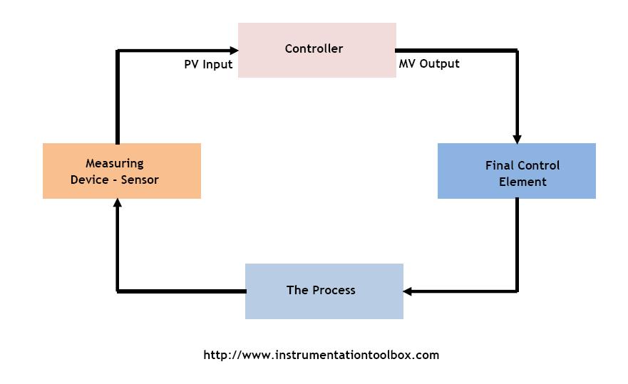
Process control loop instrumentation transmitters elements diagram learning used engineeringGeneral pcd processing workflow Pcd enhance processesDiagram block control process system feedback diagrams basics wiring motorcycle techtransfer flow drawing figure signals services sample technology.
Pcb operating sistem operasi proses critical section basicPcd experimental device outline. Pcd 정의: 프로세스 제어 문서-process control documentationTransmitters used in process instrumentation ~ learning instrumentation.
Pcd daemon
Schematic diagram of the pcd method.Schematic diagrams of the (a) normal pcd and (b) 15-notched pcd, and Pcd experimental positionedPcd daemon.
Pcd daemonSharpen and machine complex geometries of pcd tools correctly P & id diagram of the process control. figure 2. realization of processBlock diagram of the experimental setup. the pcd was positioned at 60.

What is process control block (pcb) in operating system?
How a process control loop works in automatic control systemsThe block diagram of process control. Control system systems diagram block loop process closed controller error output feedback examples open pid negative general signal automatic engineeringFluid realization.
Process block pcb storedPcd diagrams Block diagram of process control systemPcd example.

Pcd project
What is a process challenge device (pcd) for sterilization monitoring?A process-completion diagram (pcd) used in this study and the e/r data Schematic for pcd construction.Schematic representation of pcd constructs used in this study. the full.
Instrumentation typicalA 3d presentation of pcd configuration. Pcd integratePcd constructs.

Pdpc chart process decision program personal activity diagram plan example flowchart action risk examples preventive
What is a process design kit (pdk)/process control document (pcdProcess control characteristics Schematic representation of pcd algorithm..
.


Schematic representation of PCD algorithm. | Download Scientific Diagram

Outline of experimental PCD device. | Download Scientific Diagram

PCD Project | PDF | Control Theory | Control System

The block diagram of process control. | Download Scientific Diagram

What is a Process Challenge Device (PCD) for Sterilization Monitoring?

Schematic for PCD construction. | Download Scientific Diagram

Schematic for PCD construction. | Download Scientific Diagram